The study of the mechanical properties under the denture below the denture and the mucosa, after the restoration of the denture, the mechanism of the force acting on the mucosa below the denture and the bone tissue under the mucosa is of great significance. Guide the repair of the shape so that the force is within the allowable range and evaluate the damage to the supporting tissue when the force exceeds the allowable force. For many years, the determination of this force has been a concern for the prosthodontics community and medical sensor researchers, and most of the existing measurement methods include pasting a piezoresistive pressure sensor below the base of the denture, but the patch pressure resistance The elastic modulus of the pressure sensor is inconsistent with the denture base, it is not consistent with the surface of the tissue to be detected, it is also difficult to be flush with the surface of the surrounding base, and the magnitude of the measured force is relatively large, and it is difficult to determine the force distribution. . In response to these problems, a MEMS capacitive pressure sensor with a length x width x height of 2.2mmx1.8mmx0.6mm was designed using the principle of a MEMS capacitive pressure sensor, and then a method of using a distributed implanted denture base was designed. It can accurately test the distribution of forces and forces under the denture below the mucous membrane and under the mucosa. The sensor has stable structure, good measurement stability, good linearity, minimum resolution of force of 0.1g, high sensitivity, stable operation in a temperature range of 100°C to 200°C, and wide temperature application The range can be applied to the determination of the force in the harsh environment of the oral cavity.
1. The sensor's process flow sensor is realized by MEMS technology. The processes used include: oxidation, lithography, engraved etching, diffusion, ICP etching, coating, and silicon-glass bonding. The processing process mainly includes the processing technology on the silicon wafer, the processing technology on the glass, and the silicon-glass bonded processing technology.
After the semiconductor wafer is oxidized, photolithographed, etched, diffused, re-oxidized, engraved, and etched, the silicon wafer front surface process is completed, mainly including the formation of grooves and insulating layers. The reverse side is then subjected to negative photolithography, etching, forming positive and negative electrode lead lines PAD and filling grooves. Among them, the purpose of diffusion is to form a functional boro-silicon film (P+ film) of about 2m, and the silicon wafer should be cleaned before diffusion. Due to the diffusion, the silicon surface will react with oxygen to form a layer of borosilicate glass, so it must be removed. Wet etching was used to remove excess surface attached borosilicate glass. In the processing of glass, the 7740 glass wafer from Xiamen Fuxin Microelectronics Technology Co., Ltd. was selected. After photolithography and coating, the metal layer sputtered on the glass was formed as the lower plate metal electrode. After silicon-glass bonding, etching, ICP etching, and coating, the entire sensor is completed. A device integrated on a silicon chip divides the silicon chip into individual pieces for subsequent packaging and testing.
2. Package and Test In the stress test under the load of a single sensor, the method adopted by this group is: use the same material as the base of the denture base as the base, dig a small square with a length of 2mm on the resin. Pit, the sensor is buried in, and then use the same material of the condensing resin and denture base resin mixing, drop in the sensor surface package flat, so that the plane and the base plane is the same, after its solidification, you can get the surface material and The denture material has uniform coverage and is shown in Figure 1 after packaging.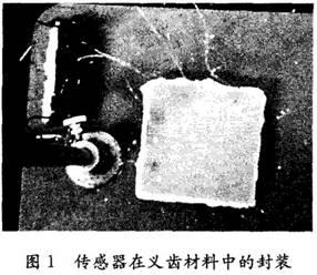
The pressure in the range of 0-90 psi is applied to the sensor implanted in the substrate and the relationship between the applied pressure and the output voltage is tested to obtain the applied pressure and output voltage as shown in FIG. 2 . The distribution relationship and polynomial fitting curve. In FIG. 2, one of the points is tested and the polynomials are fitted to each point of the test. The R-squared value of the fitted trend line is 0.9901, indicating that the voltage distribution and the fitting curve output in the test have a good Fitting degree, in the follow-up work, when the trend line is used as the external pressure and output voltage, the error value is very small.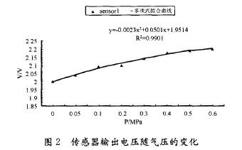
In order to complete the on-line human body test of the denture, real-time detection on the denture analog measurement device was first performed. The device leads the sensor on the artificial tooth through the lead wire to measure the force of the base and the bottom of the artificial tooth. The structure of the denture analog measurement device is shown in FIG.
The process of changing the tooth base when chewing a food with a certain hardness was measured with a denture simulation measuring device as shown in FIG. 4 .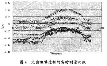
3. Conclusions The test results show that the sensor performs well, has a relatively stable input and output relationship, and can accurately measure changes in the pressure to the outside world. In addition, because the measured capacitance is relatively small, the test process is susceptible to external factors such as wire, solder joints and other interference will produce a certain error, so the next work can use the ADC to convert the analog voltage signal into a digital signal, and will use This kind of trend line with a good fit measures the corresponding software system for the application of external pressure and output voltage corresponding curve for the direct reading of data during clinical testing.
references:
[1] Zhang Kuihua Stomatology [M] Peking University Medical Press 2003
[2] Tang Hua, Gong Ping, Li Xiaojing. Implant Denture Occlusion Design[M] Foreign Medical Stomatology, 2004(5)
[3] Wang Shaoqing, Xu Ken, Feng Yongjian. Production and Test of Micro Capacitive Pressure Sensors[J] Instrument Technology and Sensors, 2005(3), 3-4
[4] Xu Zhenghong, Zhang Baowei. Comparison of flexural performance of different base resins [J] Journal of Oral Material Devices, 2004, 13(1), 8-9
Feed Tank Truck,Faw Bulk Feed Tank Truck,Bulk Feed Tank Truck,Feed Tank Trucks
HUBEI FUYA VEHICLE CO., LTD. , https://www.fuyavehicle.com